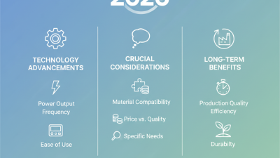
Choosing the best Ultrasonic Welder in 2026 is less about chasing the highest wattage and more about matching the machine to your parts, materials, and production pace. A compact benchtop unit may suit small batches of plastic housings. A larger system may be better for wider joints, harder materials, or repeated production runs. The details matter. Look closely at the generator’s controls, horn and fixture options, cycle monitoring, service support, and available training.
Ultrasonic welding researcher Dr. Avraham Benatar’s published work offers a useful lesson, paraphrased here rather than quoted verbatim: “Repeatable energy, pressure, and time matter more than headline power.” Buyers should treat that as a starting point, not a guarantee. Ask suppliers to weld representative parts, then inspect the joint and record the settings. A shiny sample is not enough. Check for consistent strength, clean edges, and reliable results across multiple cycles. Also confirm that the proposed horn fits your part geometry and can be maintained or replaced.
There is no universal winner. A machine that performs well on one resin or joint design may disappoint on another. That is easy to overlook when comparing brochures. This guide examines leading options by application, capability, operating cost, and support, while noting where published specifications leave unanswered questions. Test your own parts before committing. Small differences can matter.
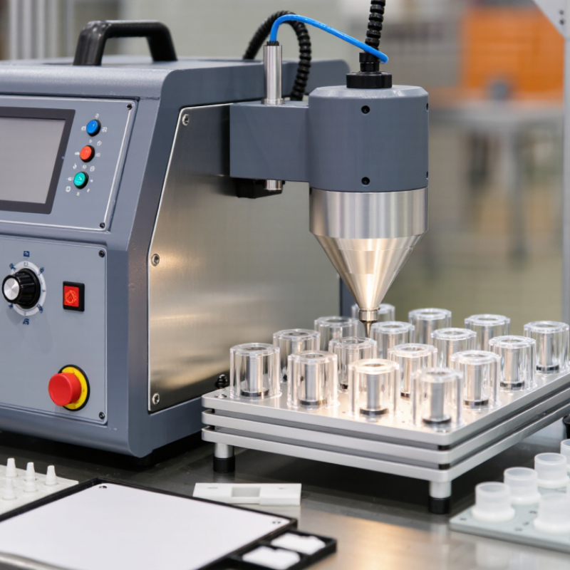
An ultrasonic welder joins materials through rapid mechanical vibration and pressure. A horn presses the parts together while vibrating, often at 20 or 35 kHz. The friction and deformation at the contact surface create heat, softening the material enough to form a bond. For many plastics, the joint forms without screws, glue, or added filler. No flame. No filler. The cycle can take less than a second, though setup and part handling add time.
The process is used for plastic housings, wire splices, and thin metal foils. The International Energy Agency’s Global EV Outlook 2024 projected about 17 million electric-car sales worldwide that year, highlighting a growing need to join battery-related components consistently. That figure is market context, not proof that ultrasonic welding suits every battery assembly. Material, thickness, joint shape, and pressure all matter. A useful trial checks weld strength and appearance across repeated cycles. If a plastic edge turns white or a foil tears, the settings or joint design may need work. It is not magic. Even a small change in part fit can weaken the result.
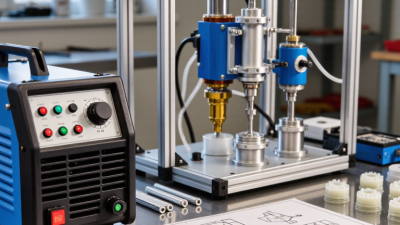
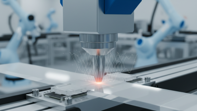
An ultrasonic welding system converts electrical energy into rapid mechanical vibration. A generator creates a high-frequency signal, and a transducer converts it into motion. A booster adjusts the vibration, while a metal horn transfers it to the parts. A fixture keeps components aligned as the horn applies controlled pressure. That is the core.
At the joint, tiny repeated movements create heat, softening compatible thermoplastic surfaces. The machine then maintains pressure while the material cools and bonds. Weld time, vibration amplitude, and force all affect the result. Too much energy can deform a part; too little may leave a weak seam. Small details matter. Part shape and material grade can change the settings needed.
Buyers should check whether the system suits their materials, joint geometry, and production rate. Controls that record energy or time can help operators repeat a validated process. Still, a polished specification sheet cannot predict every joint. A machine can look impressive and still be wrong for the part. Test representative samples, inspect the weld, and adjust settings carefully before committing to a production setup.
Compare common ultrasonic welding system types by process, typical operating range, and intended use. Specifications are representative industry ranges, not guarantees; actual requirements depend on the material, joint design, tooling, and production conditions.
| System Type | How It Works | Typical Frequency | Typical Power Range | Common Applications | Best Suited For | Key Buying Consideration |
|---|---|---|---|---|---|---|
| Benchtop pneumatic plastic welder | A generator drives a converter and booster to vibrate a horn. Pneumatic pressure brings the horn and parts together for a controlled weld cycle. | 20–40 kHz | Approximately 500–2,000 W | Small plastic housings, consumer components, packaging parts, and prototypes | Low-to-medium production volumes and a range of small assemblies | Check available force, throat depth, cycle controls, and compatibility with the required horn and fixture. |
| Servo-driven plastic welding system | A servo actuator controls the horn's movement and force. Welds can be managed by position, energy, time, or other process limits supported by the controller. | 20–40 kHz | Approximately 1,000–4,000 W | Automotive and appliance components, connectors, medical-device parts, and precision enclosures | Repeatable production where process monitoring and controlled displacement are important | Assess force and travel requirements, data logging, recipe management, and integration with automation. |
| Rotary or continuous ultrasonic system | A rotating sonotrode applies ultrasonic vibration and pressure continuously or intermittently as material passes through the tooling. | Typically 20–35 kHz | Application-dependent; often hundreds of watts to several kilowatts | Nonwoven fabrics, films, laminates, and continuous seams or patterned bonds | Web-based production requiring repeating or continuous joints | Confirm material feed speed, seam geometry, anvil design, and compatibility with the web or laminate. |
| Ultrasonic metal spot or seam welder | Vibrating tooling applies pressure and high-frequency motion to metal surfaces, creating a solid-state bond through interfacial motion and deformation rather than bulk melting. | Commonly around 20–40 kHz, depending on the system and application | Application-dependent; commonly in the kilowatt range for production equipment | Thin nonferrous foils, wire-to-terminal joints, battery tabs, and selected electrical connections | Joining suitable thin metal parts when a solid-state process is preferred | Validate metal type, thickness, joint geometry, clamping, and required bond-strength testing with application trials. |
| Stage | System Component or Action | Purpose |
|---|---|---|
| 1. Set up the joint | Parts are placed in a fixture or between the welding tooling and support anvil. | Positions and supports the parts so the intended joint area receives pressure and vibration. |
| 2. Generate vibration | An electronic generator supplies high-frequency electrical energy to a piezoelectric converter. | The converter changes electrical energy into mechanical vibration at the system's operating frequency. |
| 3. Transfer vibration | A booster and horn, also called a sonotrode, transmit and apply vibration to the workpiece. | Delivers vibration and force to the joint; tooling is designed for the specific application. |
| 4. Apply pressure and weld | The actuator holds the parts together while vibration acts at the interface. | For thermoplastics, localized heating softens or melts material at the joint. For suitable metals, vibration and pressure form a solid-state bond. |
| 5. Hold and verify | Vibration stops; pressure may be maintained briefly while the joint cools or stabilizes. The controller can monitor configured process limits. | Helps the joint set and supports consistent process control. Inspection or testing may still be needed to verify product quality. |
Buyer note: Frequency and power alone do not determine weld quality. Request application testing with the actual materials and joint design, and verify tooling, cycle requirements, safety guarding, maintenance needs, and quality-monitoring features before purchase.
Ultrasonic welders differ in how they deliver vibration and control pressure, so the right type depends on part geometry and production volume. Bench-top units clamp small components in a fixed fixture. They are common for plastic housings, medical-device assemblies, and electrical connectors. These machines suit repeatable jobs with modest output. Small batches matter.
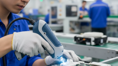
Handheld systems let an operator weld larger or awkward plastic parts, such as vehicle trim, appliance panels, and fabric seams. Automated presses integrate sensors, part nests, and conveyors for high-volume packaging closures or multi-point assemblies. Continuous rotary systems can seal thermoplastic films and nonwoven materials, though speed and material thickness must be matched carefully. Not every seam behaves alike.
Ultrasonic metal welders join thin conductive parts, including battery tabs and wire terminals, using vibration and clamping rather than melting the bulk material. They need different tooling and process settings from plastic welders. Across all types, horn shape, joint design, and consistent pressure strongly affect results. A sample run on real parts is wise; drawings alone may miss warpage, contamination, or awkward access. Real production has surprises.
When comparing 2026 ultrasonic welders, start with the parts you actually plan to join. Plastic type, joint shape, and part size can change the required power and tooling. A machine that handles small housings quickly may struggle with thicker components or uneven contact surfaces. Ask for trials using your own materials, not just sample pieces.
Look beyond the advertised cycle time. Check weld consistency across repeated runs, setup time, and how easily operators can adjust pressure, amplitude, and energy limits. Watch the horn during a real production cycle. Does it reach the joint cleanly? Are parts shifting or showing marks? Small details count. A faster cycle is not useful if rejects rise or adjustments take half a shift. I would not treat a single successful test as proof; repeat the trial with different operators and batches.
Match the system to your daily workload. High-volume lines may need quick changeovers, clear fault alerts, and data logging. A small workshop may value straightforward controls and accessible maintenance more. Check spare tooling costs, service response, and operator training before comparing quotes. That matters. Also confirm that guards and emergency stops suit the installation. Leave room for a learning curve: even a capable machine can need tuning when materials or part designs change.
The best ultrasonic welder depends on the parts you need to join, not a headline power rating. Start with the material, joint shape, and thickest section in your production run. A thin plastic cover with a narrow seam may need different tooling and pressure from a larger housing. Small details matter. Ask whether the machine can hold consistent force and alignment across your actual parts.
Match the controls to your process. Time-based settings may suit stable jobs, while energy or distance monitoring can help when part variation affects the weld. Ask what data the machine records and whether operators can adjust settings without disrupting validated jobs. Check the horn and fixture changeover process, too. A fast cycle is less useful if setup takes half a shift. I would not choose from a specification sheet alone.
Request sample welds using your own components, then inspect strength, appearance, and repeatability across several cycles. If possible, watch a production-style run, not just a single demonstration. Listen for unusual vibration and check how clearly the machine signals a poor cycle. It is easy to focus on the welder and overlook fixture costs, training, or maintenance access. I might still miss a constraint on the first pass; a short trial often reveals it.
20, 30, 35, and 40 kHz are common nominal frequency options for ultrasonic welding equipment. Frequency alone does not determine which welder is best: consider the materials, part size and geometry, required cycle time, and the machine’s power and tooling compatibility.