How to Build a DIY Ultrasonic Welder
Building a Diy Ultrasonic Welder starts with understanding the process, not copying a circuit diagram. Ultrasonic welding joins compatible materials through high-frequency vibration, pressure, and carefully controlled timing. A transducer, booster, horn, and frame must work as one system. A small alignment error can produce weak joints, overheating, or a cracked horn. It is not plug-and-play.
The field has experienced researchers, including welding engineer A. Benatar, whose published work examines ultrasonic welding and process control. I cannot verify a verbatim quotation from him, so I will not invent one. That restraint matters: a confident-sounding quote is not evidence. For a practical safety benchmark, NIOSH’s 1998 Criteria for a Recommended Standard: Occupational Noise Exposure recommends limiting workplace noise exposure to 85 dBA over an eight-hour time-weighted average. This is not a specific limit for every ultrasonic device, but it is a useful reminder to measure sound rather than guess. Small details count.
This guide will introduce the machine’s main parts, explain what each one does, and outline cautious testing with suitable materials. It will also distinguish low-voltage control circuits from the power electronics that require qualified handling. A DIY build may teach valuable lessons, yet homemade equipment can behave unpredictably. Treat every test as a measurement exercise: record settings, inspect each weld, and stop when results drift. That is less exciting than a quick success. It is also more reliable.
Understanding Ultrasonic Welding and Its Core Components
Ultrasonic welding joins compatible thermoplastics by vibrating them rapidly under pressure. The vibration creates heat at the contact surfaces, softening the plastic so the parts fuse as they cool. The energy is concentrated at the joint, often around a small ridge molded into one part. No adhesive is needed. Not glue. Material choice matters: plastics that look similar may respond differently, and mixed materials can produce weak seams. A test coupon can reveal problems before a useful part is damaged. The process sounds simple, but consistent results depend on alignment, pressure, and timing.
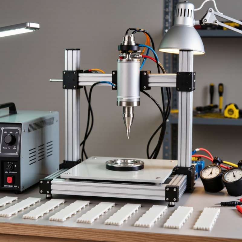
A typical system has four core components. The generator converts electrical power into a high-frequency signal. A piezoelectric transducer changes that signal into mechanical vibration. A booster transfers and adjusts the vibration, while the horn delivers it to the workpiece. A fixture holds the parts steady; even slight movement can leave an uneven seam. The horn’s shape and contact area must suit the part. This is where a DIY design can become less straightforward than expected. Ultrasonic equipment also involves electrical and mechanical hazards, so protective enclosures, reliable clamping, and appropriate shutdown controls deserve attention alongside the weld itself.
Selecting a Transducer, Booster, Horn, and Power Supply
A DIY ultrasonic welder works as a matched system, not a pile of interchangeable parts. Choose a transducer for the intended operating frequency and duty cycle, then confirm its rated power suits the materials and joint size. Piezoelectric transducers are common, but their mounting and cooling requirements still matter.
Small details matter.
A loose connection can waste energy and create heat.
The booster changes vibration amplitude, while the horn transfers it to the workpiece. Select both for the transducer’s frequency and the joint’s shape. A narrow horn may concentrate energy, but it can also mark or overheat plastic. Check that the horn face sits evenly against the parts.
A resonance analyzer can help verify the assembled stack; guessing by sound is unreliable.
I have found this stage less intuitive than it looks.
The power supply, or generator, must match the stack’s frequency and electrical requirements. Look for controlled amplitude, overload protection, and clear operating limits rather than simply choosing the highest wattage.
Keep mains wiring enclosed and grounded, and use a guarded test area; ultrasonic vibration can be difficult to notice while still causing injury.
Test with small material samples and inspect the weld, horn temperature, and repeatability. Results may vary with material and fit, so record what changes instead of assuming one setting will suit every joint.
Designing the Frame and Clamping Mechanism
How to Build a DIY Ultrasonic Welder: Designing the Frame and Clamping Mechanism
A rigid frame helps keep the horn, workpiece, and support surface aligned. Even slight movement can cause uneven contact and inconsistent welds. A thick steel plate or carefully braced frame can reduce flex, but check alignment under load rather than judging it by appearance. I once trusted a setup that looked square; pressure revealed a small tilt. It mattered.
Design the clamp to apply steady, repeatable pressure without twisting the parts. A guided lever or screw clamp can work for small test pieces, provided it moves smoothly and has a clear travel limit. Use a flat backing fixture suited to the material, and keep fingers away from the closing area. Add a guard and an accessible stop control. Ultrasonic equipment can create pinch, heat, and noise hazards, so test only with suitable protective measures and a properly rated system. The frame may need adjustment after early trials. That is normal.
Tips: Mark the workpiece position on the fixture. Check for wobble before powering the system. Change one variable at a time, and record the pressure setting and results.
Assembling and Connecting the Welder Components
A DIY ultrasonic welder depends on components that are designed to work together: a generator, transducer, booster, and welding horn. Check their rated frequency and power before assembly; mismatched parts can overheat or produce unstable vibration. Small details matter. Mount the transducer and booster in the specified order, keeping mating surfaces clean and free of burrs. Tighten threaded joints only to the component maker’s stated torque. Guessing can damage delicate threads, and I have found that “snug” is not a reliable measurement.
Keep it unplugged. Secure the assembly to a rigid frame, then check that the horn moves freely without touching nearby brackets or wiring. Connect only the specified cables, follow the wiring diagram, and provide protective grounding, strain relief, and an enclosed electrical compartment. Never work on live terminals; have a qualified electrician inspect any mains-power connections. Before testing, confirm that fasteners are tight and the work area is clear. A brief, low-risk test with a suitable sample can reveal alignment problems, though the first result may be uneven. Adjust one variable at a time and record what changes.
Common Ultrasonic Welding Frequencies
When assembling a welder, the generator, transducer, booster, and horn must be designed to operate at the same frequency.
These are common nominal frequencies for ultrasonic welding systems. The correct choice depends on the application and the matched components; frequency alone does not determine welding performance.
Testing Welds and Adjusting Settings Safely
Testing welds should begin with small, matching scraps of the intended material.
Keep the pieces flat and free of dust. Secure them in a fixture before activating the horn, and keep hands clear of the press area.
Wear eye protection, and use the machine’s guard and emergency stop. Never bypass an interlock.
Ultrasonic equipment can contain hazardous electrical energy; disconnect power and follow the design’s discharge procedure before opening or adjusting it. Capacitors may retain a charge.
Make one adjustment at a time, such as pressure, weld duration, or amplitude, and change it only within the equipment’s documented limits. Test a fresh pair of scraps after each change. Let the joint cool, then inspect for gaps, scorching, thinning, or a clean separation under gentle hand pressure.
A neat surface can still hide a weak bond.
Record the settings and result, even if the notes look untidy. That small habit makes comparisons more reliable.
Stop if the horn shifts, the fixture loosens, or the machine behaves unexpectedly.
Recheck alignment only with power disconnected. One missed note can waste a batch.