Leave Your Message

China Top Gray Ultrasonic Welder Manufacturer and Supplier

China’s ultrasonic welding industry serves manufacturers seeking repeatable joining for thermoplastics and selected nonwoven materials. A Gray Ultrasonic Welder can suit production lines where clean seams, short cycle times, and controlled energy matter. Small details count. The machine’s color does not establish its quality; sound engineering and verified process results do.

When comparing a Chinese manufacturer or supplier, buyers should look beyond catalog photos. Ask about operating frequency, generator control, horn design, fixture support, safety features, and after-sales guidance. Request a sample weld using the intended material and joint geometry. Then inspect its strength, appearance, and cycle consistency. Results depend on resin type, part design, pressure, amplitude, and setup. No single setting suits every application.

Experienced suppliers can explain these trade-offs clearly and document their equipment’s capabilities and limitations. Check for commissioning support, spare-part access, and practical operator training. A polished quotation is useful, but it is not proof. Confirm production capacity and test procedures before ordering. Even a well-built welder may need adjustment on a real line. This guide outlines questions for identifying a dependable China-based Gray Ultrasonic Welder manufacturer and supplier, with performance claims grounded in application-specific evidence.
China Top Gray Ultrasonic Welder Manufacturer and Supplier

Overview of Gray Ultrasonic Welders and Their Role in Manufacturing

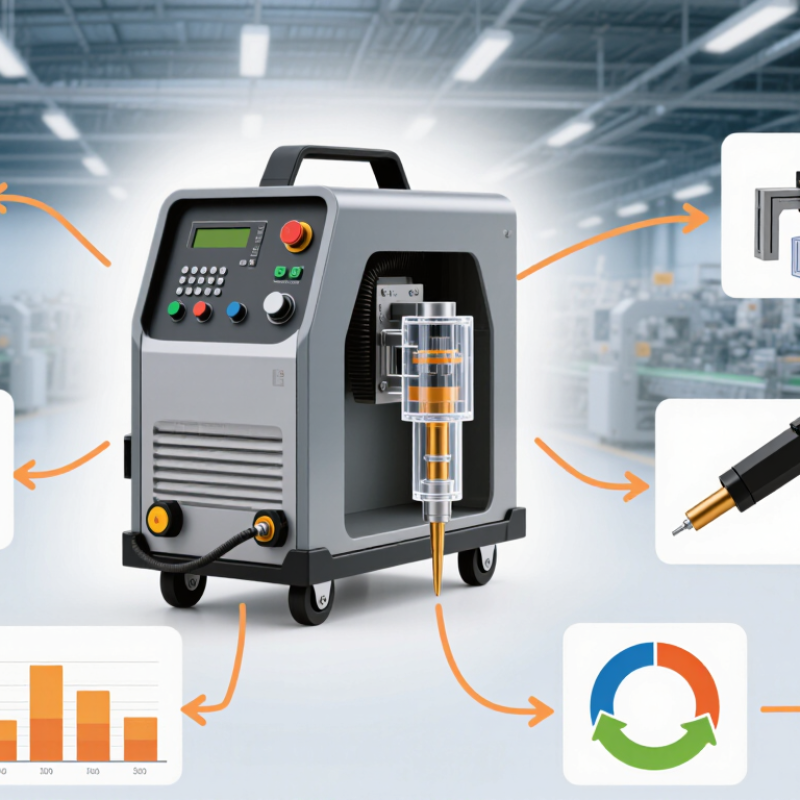
Gray ultrasonic welders use high-frequency mechanical vibration and controlled pressure to join compatible thermoplastic parts. Their gray housings are practical in busy production areas, where dust and handling marks show quickly. The color itself does not determine weld quality. Amplitude, force, time, and part design matter more. A well-set cycle can create a clean joint without screws or liquid adhesive.

In manufacturing, these systems are used for small housings, wire assemblies, packaging components, and nonwoven materials. An operator places two parts in a fixture, then the horn presses them together as vibration generates localized heat. The cycle often lasts seconds, but repeatability depends on stable materials, suitable tooling, and accurate alignment. A slight mismatch can leave a weak seam or visible marks. That happens.

For reliable use, teams should test sample parts before setting production limits. Record weld settings, inspect joint appearance, and check strength with an appropriate test method. Maintenance matters too: worn horns, loose fixtures, or inconsistent air pressure can change results. Not every plastic combination bonds well, and complex parts may need redesigned joints. This is easy to overlook. Gray ultrasonic welders can support efficient assembly, but process validation—not appearance—should guide equipment selection and production decisions.
Gray Ultrasonic Welders: Common Operating Frequencies

Ultrasonic plastic welding systems commonly use nominal frequencies such as 15, 20, 30, 35, and 40 kHz. The best frequency depends on the material, part geometry, joint design, and tooling; frequency alone does not determine weld quality. The welder’s gray exterior is a product finish and does not indicate its operating frequency.

How Gray Ultrasonic Welding Machines Work

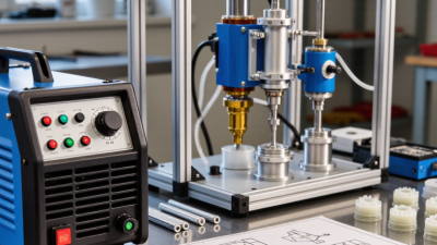
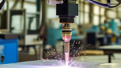
A gray ultrasonic welding machine joins compatible thermoplastics using rapid mechanical vibration and controlled pressure. Its gray housing is only an exterior finish; the working process happens inside the tool assembly. An electronic generator supplies high-frequency energy to a transducer, which converts it into vibration. A booster carries that motion to the horn, also called the sonotrode.

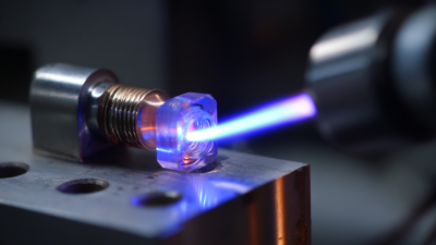
The horn presses two plastic parts together while vibrating, often thousands of times per second. At their joint, the motion creates heat through friction and material deformation. The small contact area softens, then the machine stops vibrating and maintains pressure as the material cools. The result is a bonded joint, often formed within seconds. No glue is needed.

Settings matter. Amplitude, pressure, weld time, and joint shape must suit the material and part design. Too little energy can leave a weak seam; too much may mark or deform the surface. A practical setup starts with sample parts and checks the joint after welding. Look for consistent fusion, not just a neat appearance. Different plastic grades can behave differently, so a setting that works once may not transfer perfectly. That detail is easy to miss.

Main Components and Technical Features

A gray ultrasonic welder converts electrical energy into high-frequency mechanical vibration. Its main assembly includes a generator, piezoelectric transducer, booster, and sonotrode, commonly called the horn. The generator creates the signal; the transducer turns it into vibration. The booster adjusts vibration amplitude, while the horn transfers energy to the joint. A rigid frame and pneumatic or servo press provide controlled force. The fixture supports the workpiece and helps keep parts aligned.

The control system may set weld time, energy, amplitude, and trigger pressure. Some models also monitor displacement or peak power, helping operators spot changes between cycles. These readings are useful, but they do not guarantee a sound joint. Material type, part geometry, surface condition, and fixture fit all affect results. A setup that works on one component may need adjustment on another. Real production is sometimes less tidy than a specification sheet suggests. Inspect horn wear and confirm alignment during routine checks.

Tips: Keep the mating surfaces clean and the fixture secure. Test settings on representative parts before regular production. Small changes in pressure or amplitude can alter the joint.

Manufacturing and Quality Control in China

Manufacturing a gray ultrasonic welder in China calls for controls at each stage, not just a final power-on check. Incoming converters, horns, and electronic components should be inspected against specifications. During assembly, technicians can record torque, wiring checks, and calibration results by unit. Small details matter. A horn face with slight wear may change how energy reaches the joint. Operators should log amplitude, pressure, trigger force, and weld time for each setup, then test sample welds using pull or peel methods.

China’s industrial scale makes repeatable inspection especially important. The International Federation of Robotics’ World Robotics 2024 report recorded 276,288 industrial robot installations in China in 2023, representing 51% of global installations. That figure describes automation, not ultrasonic-welder quality. ISO’s Survey of Management System Standard Certifications for 2022 recorded more than 1.2 million ISO 9001 certificates worldwide; certification supports documented processes but does not guarantee every weld. A reliable supplier should retain calibration records, inspection results, and traceable component batches. Repeat the test. Even careful production has variation, and a fixture can sit slightly out of alignment. That is easy to miss, so periodic checks matter.

China Top Gray Ultrasonic Welder Manufacturer and Supplier - Manufacturing and Quality Control in China
Manufacturing Stage Control Dimension Inspection or Test Method Acceptance Basis and Recorded Data
Design review Application, workpiece material, joint design, cycle requirements, and machine safety Review the approved drawings, customer requirements, risk assessment, and intended operating conditions before production. Document the approved machine configuration, tooling interface, operating limits, and applicable safety requirements. Confirm that the proposed setup is suitable for the specified workpiece and process.
Incoming materials and components Frame, electrical components, pneumatic components, transducer, booster, and horn Verify part numbers against the approved bill of materials; inspect visible condition and check dimensions or certificates where specified. Components must match approved purchasing and drawing requirements. Record inspection status, supplier lot or serial references where applicable, and any nonconformance disposition.
Frame and mechanical assembly Mounting dimensions, alignment, fasteners, moving parts, and surface finish Use measuring tools and assembly checklists; inspect the press, guide system, fixture interface, and enclosure for fit and movement. Dimensions and alignment must meet the approved drawings. Moving parts must operate without binding, and fasteners must be secured according to the assembly specification.
Gray finish and enclosure Color consistency, coating coverage, edges, and visible surface condition Visual inspection under suitable lighting; compare with the approved finish sample or color reference when one is specified. Coating should be reasonably uniform and free from unacceptable peeling, exposed substrate, or damage. Color acceptance should follow the agreed reference; no universal gray color value applies to every machine.
Ultrasonic stack assembly Transducer, booster, horn, threaded connections, and resonance behavior Check component compatibility, connection condition, tightening procedure, and generator diagnostics using the machine’s approved setup procedure. The assembled stack must operate within its specified frequency and tuning limits. Frequency is application-dependent; common industrial systems use nominal frequencies such as 20, 30, 35, or 40 kHz, but these are not interchangeable specifications.
Electrical installation Wiring, grounding, protection devices, connectors, and control functions Inspect wiring against schematics and perform the electrical checks required by the approved test plan and destination-market requirements. Wiring and protective measures must match the design. Record test results and equipment identification. IEC 60204-1 may be relevant to machinery electrical equipment; applicability and required tests depend on the machine and market.
Safety function verification Emergency stop, guards, interlocks, and risk-reduction measures Function-test installed safety devices and compare results with the machine risk assessment and approved control design. Safety functions must behave as specified in the design. ISO 12100, ISO 13850, and ISO 13849-1 may be relevant references; citing a standard does not by itself establish certification or conformity.
Generator and control setup Operating frequency, amplitude setting, weld mode, time, energy, and pressure settings Verify available settings and alarms using the control interface; confirm the configured recipe against the approved process setup. Record the selected process parameters and recipe version. Settings must remain within the equipment and application limits; actual values are determined by the machine configuration and workpiece trials.
Functional run-off Actuation, cycle sequence, display, alarms, and repeat operation Run the machine through the approved functional test sequence and verify the press, controls, and fault responses. Each tested function must match the approved sequence. Record the test date, machine serial reference, test results, and any corrective actions.
Sample welding validation Joint appearance, weld strength, dimensions, and leak performance where required Weld representative customer or qualification samples and inspect or test them using the agreed method, such as visual inspection, pull testing, or leak testing. Acceptance limits must come from the customer drawing, product specification, or validated process plan. Weld quality cannot be guaranteed by a single universal strength or cycle-time value.
Final inspection and shipment preparation Machine configuration, accessories, documentation, labeling, and packaging Compare the completed machine with the order and packing list; inspect protective packaging and verify included manuals and records. Record the final inspection status and supplied items. Packaging should protect the equipment during the specified handling and transport conditions.
Quality note: Inspection limits, test procedures, certifications, and applicable standards should be confirmed for the specific machine model, customer specification, and destination market. The process ranges and references above are general manufacturing guidance, not a claim that every machine has been independently certified.

Industrial Applications and Supplier Evaluation Criteria

Ultrasonic welding is used to join compatible thermoplastics without adding screws or liquid adhesive. In packaging, it can seal small containers and bond film components. Electrical assemblies may use it for wire splices or plastic housings. A gray control cabinet is only an appearance choice; it says little about weld quality. Small details matter. Material grade, joint shape, horn condition, and clamping pressure can all affect the result. Test real production parts, not just sample coupons. Thin walls may deform, while uneven surfaces can produce weak seams. These outcomes are easy to miss in a quick demonstration.

When evaluating a supplier, ask how they assess your parts and define a repeatable process window. Request trial records showing weld time, force, and inspection results. A useful trial includes difficult parts, not only ideal ones. Check whether the supplier can explain tooling choices and recommend adjustments when results vary. Confirm machine specifications, safety guarding, operator training, spare-part access, and service response times. Ask for clear maintenance instructions and documentation that your team can use on the factory floor. A polished presentation is not proof of reliable support. No checklist catches every mismatch, so keep some time and budget for validation after installation.