Leave Your Message
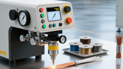
Selecting a China-made Ultrasonic Welder For Wire starts with the joint, not the brochure. Wire diameter, strand count, insulation, and production speed all affect the process. A copper cable used in a vehicle harness may need different tooling and pressure from a fine battery lead. Small setup changes matter.
Demand is changing. The International Energy Agency’s Global EV Outlook 2025 expects electric car sales to exceed 20 million worldwide that year, representing more than one-quarter of new car sales. That forecast signals expanding electrification, but it does not measure ultrasonic welder demand or wire-joint volumes directly. That distinction matters. For manufacturers, it supports examining joining capacity without treating market growth as a guaranteed equipment order.
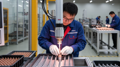
Ultrasonic metal welding can create solid-state wire joints without added solder, when the materials and settings are suitable. Buyers should ask suppliers for application trials, weld-strength results, cycle-time records, and clear maintenance guidance. A clean sample joint is useful; repeatable results across shifts are more persuasive. Not every joint. Wire preparation, horn wear, and operator setup can still undermine production, even with a capable machine. That deserves scrutiny.
This guide examines Chinese ultrasonic wire welders through practical criteria: material compatibility, control features, service support, and verifiable test evidence. It avoids ranking a machine on claims alone. No single specification tells the whole story. Manufacturers should validate their own wire, output targets, and quality checks before choosing equipment.
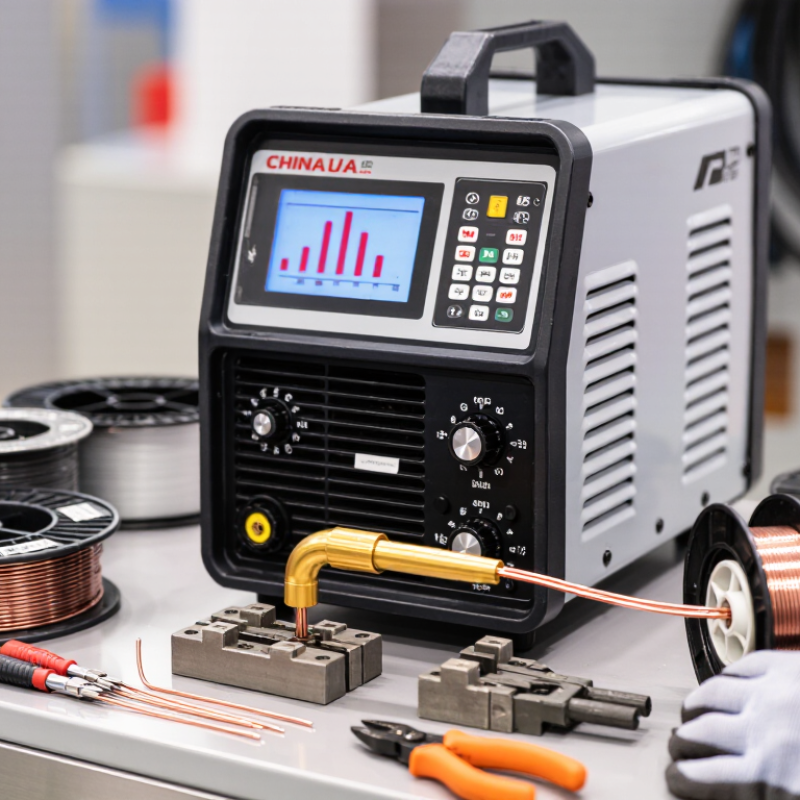
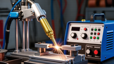
Ultrasonic wire welding is a solid-state joining process. A clamping force holds stripped wire ends between a vibrating sonotrode and a supporting anvil. High-frequency motion runs across the joint, disrupting surface films and deforming tiny contact points. The metals bond without forming a conventional molten pool. No filler metal is added. In practice, weld quality depends on vibration amplitude, pressure, time, and the wire’s material and strand geometry. Too little energy may leave a weak joint; too much can flatten or damage strands.
The American Welding Society’s Welding Handbook describes ultrasonic welding among solid-state joining processes. For market context, Grand View Research valued the global ultrasonic welding market at about USD 1.1 billion in 2023 and forecast a 5.4% compound annual growth rate from 2024 to 2030. That figure covers ultrasonic welding broadly, not wire welding alone. A production setup should therefore be validated with the actual cable, cut length, and pull-test method. It is not foolproof. Small changes in strand lay or oxide condition can shift results, and tuning is sometimes less repeatable than expected.
| Dimension | Description | Typical Details |
|---|---|---|
| Definition | Ultrasonic wire welding is a solid-state joining process that uses high-frequency mechanical vibration and clamping force to bond metal wires or wire bundles. | Commonly used for electrical connections and wire-to-terminal or wire-to-wire joints. |
| Core joining principle | Vibration causes controlled relative movement at the contact surfaces. Together with pressure, this movement disrupts surface films and promotes intimate metal-to-metal contact and bonding. | The joint forms mainly through interfacial deformation and bonding, rather than bulk melting. |
| Common materials | The process is widely applied to conductive, ductile metals. Copper and aluminum are common examples in wire and cable applications. | Suitability depends on alloy, temper, surface condition, wire construction, and joint design. |
| Wire configurations | Equipment and tooling can be configured for solid wires, stranded wires, wire bundles, and selected wire-to-terminal joints. | The appropriate configuration and capacity must be verified for the conductor cross-section and joint geometry. |
| Vibration frequency | The transducer converts electrical energy into mechanical vibration, which is transmitted through the tooling to the joint. | Industrial ultrasonic welding systems commonly operate at frequencies such as 20, 30, or 40 kHz; the selected frequency depends on the equipment and application. |
| Main process inputs | Weld performance is influenced by vibration amplitude, applied force, weld time or energy, tooling pattern, and workpiece positioning. | Settings are application-specific and should be established through process trials and validation. |
| Typical process sequence | Position the conductors, clamp them with the tooling, apply ultrasonic vibration under force, stop the vibration at the programmed endpoint, and release the joint. | Cycle time varies with the material, conductor size, equipment, and weld settings. |
| Heat and melting | Heat is generated locally by friction and deformation at the interface, but the process is designed to create a solid-state joint rather than melt the bulk conductors. | The actual temperature depends on the materials and process conditions. |
| Advantages | The process can produce compact electrical joints without filler metal and is suitable for automated production when the application is properly developed. | Benefits depend on conductor design, production requirements, and validated process capability. |
| Quality checks | Joint evaluation may include visual inspection, pull or tensile testing, electrical resistance measurement, and monitoring of process data. | Acceptance limits should be set according to the product specification and applicable industry requirements. |
| Key setup considerations | Consistent wire preparation, alignment, clamping, and tooling condition help maintain repeatable contact and weld quality. | Oxidation, contamination, strand movement, and worn or unsuitable tooling can affect results. |
| Note: The technical details above are general process guidance. Equipment capacity, operating parameters, and acceptance criteria should be confirmed for each material and joint application. | ||